COMMAND CENTER
Universal Software Platform for Advanced Features & Settings
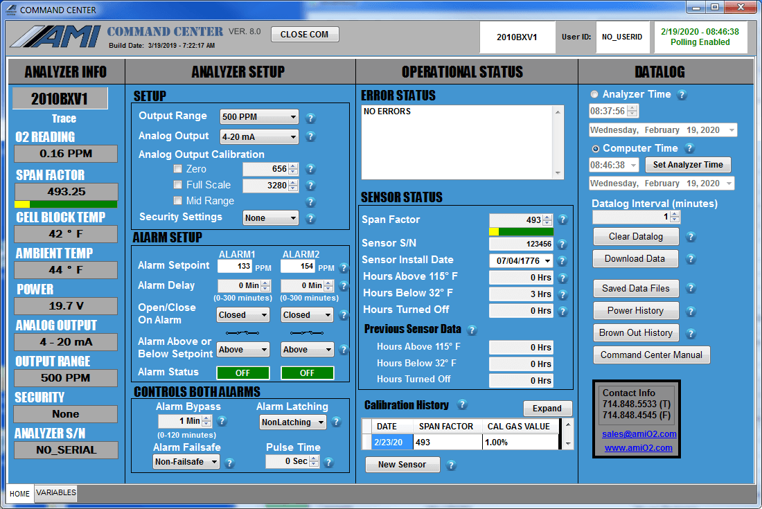
The COMMAND CENTER is a special electronics platform developed by AMI that give users access to advanced functions not available on other competitive devices. It is a universal platform that works across AMI’s Gas Measurement Analyzers. Once you open the software on your laptop and connect the laptop to the Analyzer, the COMMAND CENTER will automatically recognize your Analyzer and reconfigure to only display those settings and cells specific to your Analyzer.
REGISTER NOW And Get a FREE Download of the COMMAND CENTER
Analyzer Information
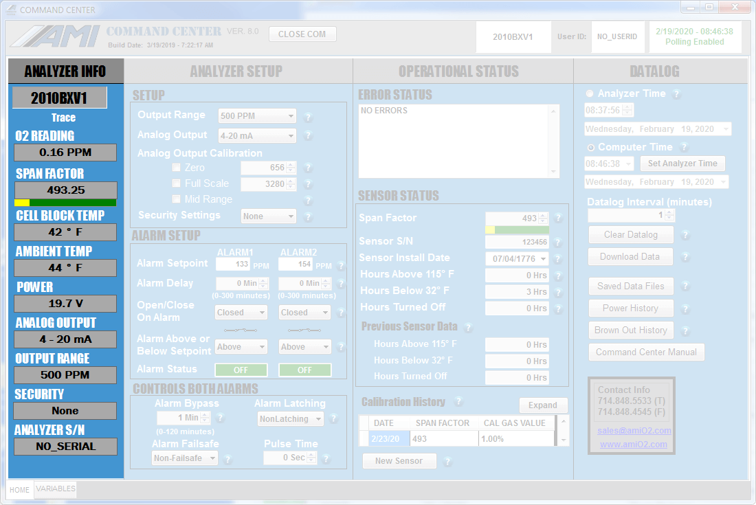
The ANALYZER INFO Column will display the following information about your Analyzer
- Analyzer model Number
- Measurement reading
- Span Factor (not available on the MODEL 4010BR)
- Cell Block Temperature
- Ambient Temperature
- Input Power, either AC or DC
- Analog Output Setting (4 – 20 mA or 1 – 5 VDC)
- Output Range Selection
- Security Selection
- Analyzer Serial Number
Analyzer Setup Area
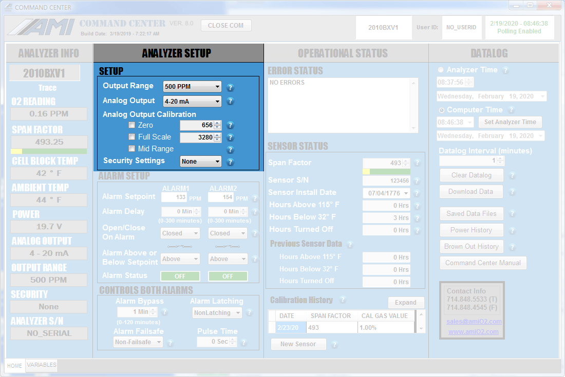
This section allows the operator to select one of three security settings to prevent unauthorized changes to the Analyzer’s settings using the front panel.
The analog output setting of the Analyzer is set and calibrated at the factory per the customer’s requirements. If the customer wants to make a change from 4 – 20 mA to 1 – 5 VDC or vice versa, it is done here.
Analyzer Logic & Setup
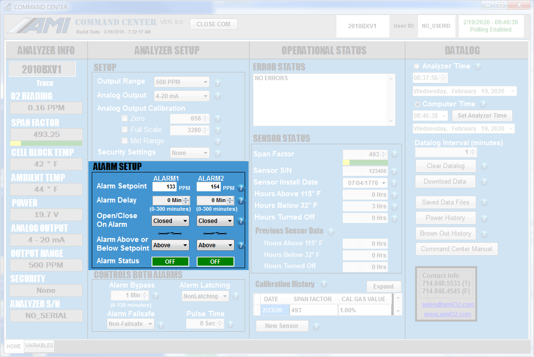
AMI Advanced Gas Analyzers feature 2 independent concentration alarms with individual settings for:
- Setpoints
- Relay contacts
- Close/Open logic
- Alarm delays
All these can be adjusted and set in this area.
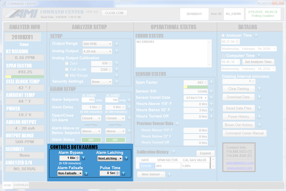
Controls for Both Alarms
This section provides access to settings that will affect both alarms and cannot be set independently for each alarm. They include:
- Alarm Bypass
- Alarm Latching
- Alarm Failsafe/Non-failsafe
- Pulse Time
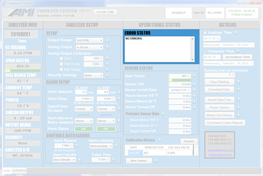
Error Status Display
This area displays any existing error(s) detected by the Analyzer. Each error has an assigned number and message. Once troubleshooting is completed and the error is resolved, the message will automatically be removed from the Error Status Display by the Analyzer.
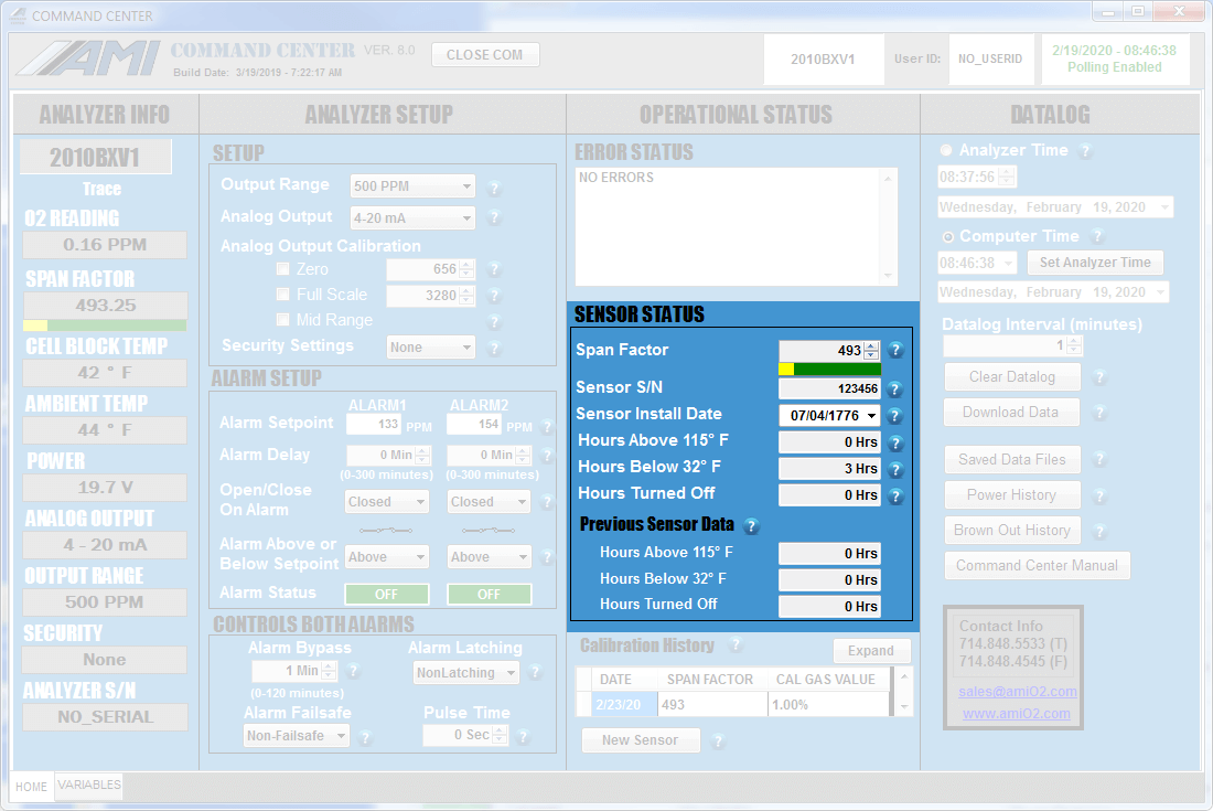
Sensor Status
This section stores and displays information on the sensor currently installed in the Analyzer. Among the useful information are the Span Factor and date of installation.
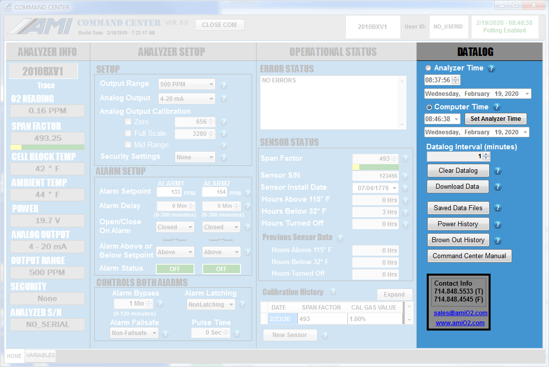
Datalog Setup
Automatic data logging provides detailed time-stamped records of gas measurement, gas pressure, temperature, supply voltage and power brown-out history. The default setting is for 1-minute intervals over 15 days. If the duration of the interval is increased, the data collection period will also increase proportionally.
REGISTER NOW And Get a FREE Download of the COMMAND CENTER
